

Vol.30 THE ORDERING GUIDE(1)
"HOW TO INSTRUCT SHAPE AND DIMENSIONS"
This time, we summarized the instructions and precautions when ordering tools.
The way to instruct a required dimension and shape
Please specify the tool shape and dimensions based on the following punch shape and dimensions table.
Also, for shapes other than those shown in the table below,
please specify with a drawing attached.
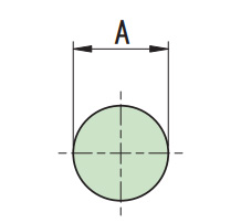
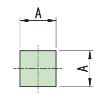
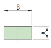
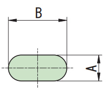
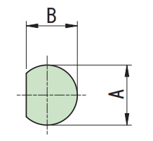
| Punch shape | Round (RO) | Square (SQ) | Rectangle (RE) | Obround (OB) |
| Figure of punch shape |
|
|
|
|
| Way to instruct | φA | A x A | A x B | A x B |
| Example | φ10 | 10 x 10 | 5 x 20 | 5 x 20 |
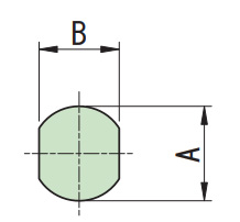
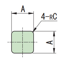
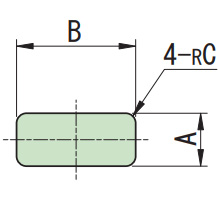
| SD | WD | Square with radius | Rectangle with radius | CN-42 |
|
|
|
|
|
| φA x B | φA x B | A x A R = C | A x B R = C | A x A R = C |
| φ20 x 16 | φ20 x 16 | 10 x 10 R = 2 | 6 x 20 R = 1.5 | 10 x 10 R = 4 |
| Punch shape | Round (RO) |
| Figure of punch shape |
|
| Way to instruct | φA |
| Example | φ10 |
| Square (SQ) | Rectangle (RE) |
|
|
|
| φA | A x A |
| φ10 | 10 x 10 |
| Obround (OB) | SD |
|
|
|
| A x B | φA x B |
| 5 x 20 | φ20 x 16 |
| WD | Square with radius |
|
|
|
| φA x B | A x A R = C |
| φ20 x 16 | 10 x 10 R = 2 |
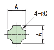
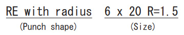
| Rectangle with radius | CN-42 |
|
|
|
| A x B R = C | A x A R = C |
| 6 x 20 R = 1.5 | 10 x 10 R = 4 |
Example instruction for ordering
HOW TO INSTRUCT THE CLEARANCE
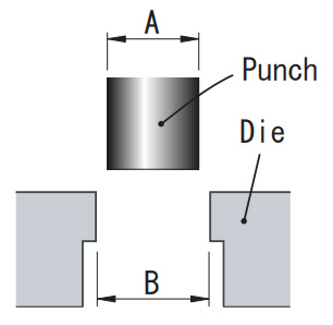
When specifying the clearance of the die, please indicate whether it is a clearance on both side or one side. Or you can also specify dimensions with clearance.
| Name of clearance | Detail |
| Both side | B - A |
| Single side | (B - A)÷ 2 |
| Clearannce included | B dimension |
< Notice >
For standard clearances, the nominal dimension is the dimension of the punch,
but in the case of the blank type (minus clearance), the nominal dimension is the dimension of the die.
| Dimension description | Punch dimension | Die dimension | |
| Clearance for both side | φ20 C = 0.3 | φ20 | φ20.3 |
| Minus clearance | φ20 minus C = 0.3 | φ19.7 | φ20 |
[Reference] METHOD FOR MEASURING CLEARANCE
Please calculate the clearance referring to the table below.
Clearance for both side = material thickness x clearance ratio
< Notice >
- 1.The shear resistance should be about 80% of the tensile strength.
- 2.For thick plates (exceeding t3.2), use the above calculation result × 1.4 as a guide.
- 3.The minimum clearance is determined by the machine specification.
- 4.Please also refer to Technical Guide Vol.6 “For clearance of the cutting die”.
| Material | Clearance Ratio | Tensile Strength (N/㎟) |
|
|
Servo / Hydraulic Machine (EM,AE etc) |
Mechanical Machine (Pega,Coma etc) |
||
| Cold rolled steel | 0.2 -0.25 | 0.15 | Over 270 |
| Hot rolled steel | |||
| Structure steel | 0.2- 0.3 | 0.2 | 400 - 510 |
| Stainless steel (soft) | Over 520 | ||
| Stainless steel (hard) | Over 450 | ||
| Alminium(Soft) | 0.15 - 0.2 | 0.1 | Over 95 |
| Aluminum (hard) | Over 215 | ||
| Copper | 0.2 - 0.25 | 0.15 | Over 275 |
| Brass(soft) | 0.2 - 0.3 | 0.2 | Over 410 |
| Brass(hard) | Over 590 | ||
-
vol.1 COUNTERMEASURES FOR SLUG PULLING IN PUNCHING PROCESS
-
vol.2 LIFE COUNTERMEASURE FOR TOOLING
-
Vol.3 TOOL MAINTENANCE
-
Vol.4 FORMING TOOL
-
Vol.5 MATERIAL FOR TOOLING
-
Vol.6 FOR CLEARANCE OF THE CUTTING DIE
-
Vol.7 ABOUT TURRET PUNCH PRESS MACHINE
-
Vol.8 VARIOUS KINDS OF SPECIAL SHAPE
-
Vol.9 PARTS NAME OF STANDARD TOOLING
-
Vol.10 EACH NAMES OF FORMING TOOL
-
Vol.11 MATERIAL PROPERTIES (STEEL)
-
Vol.12 MATERIAL PROPERTIES
-
Vol.13 CALCULATION FORMULAS FREQUENTLY USED IN SHEET METAL
-
Vol.14 HEIGHT ADJUSTMENT FREE TOOL
-
Vol.15 HOW TO DRAW AND READ DRAWINGS
-
Vol.16 HOW TO DRAW AND READ DRAWING (PRACTICAL USE)
-
Vol.17 SHAPE INSTRUCTION FOR FORMING TOOLS(1)
-
Vol.18 SHAPE INSTRUCTION FOR FORMING TOOLS(2)
-
Vol.19 CODE MANAGEMENT
-
Vol.20 BENDING TECHNICAL INFORMATION
-
Vol.21 TECHNICAL COUNSELING FAQ(1) "COUNTERMEASURES FOR GALLING"
-
Vol.22 TECHNICAL COUNSELING FAQ(2) "BURRING FOR THREAD FORM"
-
Vol.23 TECHNICAL COUNSELING FAQ(3) "PITCH OF SINGLE PIERCING"
-
Vol.24 TECHNICAL COUNSELING FAQ(4) "SHEAR OPTIONS"
-
Vol.25 TECHNICAL COUNSELING FAQ(5) "HOLDING MARK"
-
Vol.26 TECHNICAL COUNSELING FAQ(6) "SOLUTION FOR SLUG PULLING OF A SHEET METAL WITH PROTECTIVE FILM"
-
Vol.27 TECHNICAL COUNSELING FAQ(7) "MATERIAL WARPING PREVENTION DURING"
-
Vol.28 TECHNICAL COUNSELING FAQ(8) "WARPING PREVENTION OF BLANKING OUT"
-
Vol.29 TECHNICAL COUNSELING FAQ(9) "COUNTERSINK FOR COUNTERSUNK SCREW"
-
Vol.30 THE ORDERING GUIDE(1) "HOW TO INSTRUCT SHAPE AND DIMENSIONS"
-
Vol.31 THE ORDERING GUIDE(2) "REFERENCE KEY DIRECTION"
-
Vol.32 THE ORDERING GUIDE(3) "ANGLE INDICATION OF ANGLED TOOL"
-
Vol.33 THE ORDERING GUIDE(4) "SELECT SPECIFICATION OF PUNCH"
-
Vol.34 THE ORDERING GUIDE(5) "DIE SPECIFICATION SELECTION"