

Vol.10 EACH NAMES OF FORMING TOOL
When forming processing by a turret punch press, adjustments different from punching is required.
This time, We summarized the part names and functions of forming tool and how to adjust the tool.
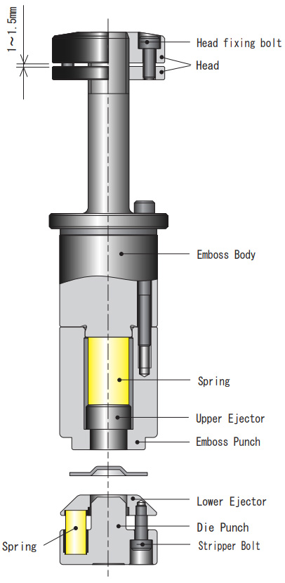
UPWARD FORMING TOOL
Upward forming is a process that forms from the down side of the workpiece upward.
EACH PART NAMES AND FUNCTIONS OF UPPER TOOLING (PUNCH SET)
① EMBOSS PUNCH
A part that directly forms a workpiece.
② EMBOSS BODY
A part that holds the emboss punch.
③ UPPER EJECTOR
A part to eject formed shape after processing.
In addition, there are also cases in which the workpiece is formed as an aid.
④ HEAD
The part that directly receives the force of the striker and transmits it to the embossed body and punch.
Also, adjust the punch length to determine the rising height of the forming shape.
How to adjust the punch length. (Height Adjustment)
- 1.Loosen the head fixing bolts.
- 2.Rotate the head and adjust length of punch.
(Clearance between upper head and lower head keep 1mm to 1.5mm.) - 3.Fasten the head fixing bolts equally.
EACH PART NAMES AND FUNCTIONS OF LOWER TOOLING (DIE SET)
⑤ DIE PUNCH
A part that directly forms a workpiece.
⑥ LOWER EJECTOR, SPRING
During processing, hold the workpiece, and after processing,
push up the lower ejector by the force of the spring and pull the workpiece away from the die punch.
⑦ STRIPPER BOLT
A part that connects the die punch and the lower die ejector.
Height of forming tool die tends to be higher than standard tool die. For that reason, it scratches a material or forming part would be hit to Upper Turret. Appropriate processing method and programing are needed.
<Reference> Adjustment amount of head
| Screw size and pitch | Adjustment amount per 1/4 rotation |
| M12×P1.25 | 0.3mm |
| M20×P1.5 | 0.4mm |
| M30×P2.0 | 0.5mm |
| M40×P2.0 | 0.5mm |
〔 TOOLING STRUCTURE (NC 1-1/4) 〕
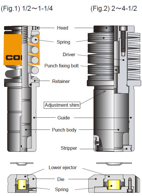
DOWNWARD FORMING TOOL
Downward forming is a process that forms from the top of the workpiece downward.
EACH PART NAMES AND FUNCTIONS OF UPPER TOOLING (PUNCH SET)
For the part names and functions of the upper tooling, refer to “PART NAMES OF THE STANDARD TOOLING” (Vol. 9).
The method of adjusting the punch length depends on the tool structure.
METHOD OF ADJUSTING PUNCH LENGTH FOR Fig.1
- 1.Attach cap screw to the two bolt holes and tighten evenly.
- 2.Rotate the head by the belt wrench and adjust the punch length.
- 3.Remove the cap screw.
Adjusting punch length for Fig.2
- 1.Loosen a punch fixing bolt.
- 2.Remove a punch body from a guide and put shims on between the punch and driver.
- 3.Install the punch body and fasten the punch fixing bolt.
NOTE
When making fine adjustment, first adjust with die-shim,
remove the die shim after the adjustment is finished,
you can easily adjust by using the same thickness punch shim to punch side.
EACH PART NAMES AND FUNCTIONS OF LOWER TOOLING (DIE SET)
① DIE
A part to form a material directly.
② LOWER EJECTOR
Push up a forming after processing.
③ SPRING
Push up the ejector.
IMPORTANT NOTICE
-
1.Use in a predetermined machining conditions.
Excessive load may be applied to the tool and damage may be caused if the punch overall length is increased for use other than the specified plate thickness (material) or to raise the rise higher than the predetermined tooling dimension. - 2.Even for presses of the same model, the shut height differs for each machine, so please adjust the appropriate punch length.
- ※At shipment from factory, we set the punch length shorter for safety.
PDF Download
-
vol.1 COUNTERMEASURES FOR SLUG PULLING IN PUNCHING PROCESS
-
vol.2 LIFE COUNTERMEASURE FOR TOOLING
-
Vol.3 TOOL MAINTENANCE
-
Vol.4 FORMING TOOL
-
Vol.5 MATERIAL FOR TOOLING
-
Vol.6 FOR CLEARANCE OF THE CUTTING DIE
-
Vol.7 ABOUT TURRET PUNCH PRESS MACHINE
-
Vol.8 VARIOUS KINDS OF SPECIAL SHAPE
-
Vol.9 PARTS NAME OF STANDARD TOOLING
-
Vol.10 EACH NAMES OF FORMING TOOL
-
Vol.11 MATERIAL PROPERTIES (STEEL)
-
Vol.12 MATERIAL PROPERTIES
-
Vol.13 CALCULATION FORMULAS FREQUENTLY USED IN SHEET METAL
-
Vol.14 HEIGHT ADJUSTMENT FREE TOOL
-
Vol.15 HOW TO DRAW AND READ DRAWINGS
-
Vol.16 HOW TO DRAW AND READ DRAWING (PRACTICAL USE)
-
Vol.17 SHAPE INSTRUCTION FOR FORMING TOOLS(1)
-
Vol.18 SHAPE INSTRUCTION FOR FORMING TOOLS(2)
-
Vol.19 CODE MANAGEMENT
-
Vol.20 BENDING TECHNICAL INFORMATION
-
Vol.21 TECHNICAL COUNSELING FAQ(1) "COUNTERMEASURES FOR GALLING"
-
Vol.22 TECHNICAL COUNSELING FAQ(2) "BURRING FOR THREAD FORM"
-
Vol.23 TECHNICAL COUNSELING FAQ(3) "PITCH OF SINGLE PIERCING"
-
Vol.24 TECHNICAL COUNSELING FAQ(4) "SHEAR OPTIONS"
-
Vol.25 TECHNICAL COUNSELING FAQ(5) "HOLDING MARK"
-
Vol.26 TECHNICAL COUNSELING FAQ(6) "SOLUTION FOR SLUG PULLING OF A SHEET METAL WITH PROTECTIVE FILM"
-
Vol.27 TECHNICAL COUNSELING FAQ(7) "MATERIAL WARPING PREVENTION DURING"
-
Vol.28 TECHNICAL COUNSELING FAQ(8) "WARPING PREVENTION OF BLANKING OUT"
-
Vol.29 TECHNICAL COUNSELING FAQ(9) "COUNTERSINK FOR COUNTERSUNK SCREW"
-
Vol.30 THE ORDERING GUIDE(1) "HOW TO INSTRUCT SHAPE AND DIMENSIONS"
-
Vol.31 THE ORDERING GUIDE(2) "REFERENCE KEY DIRECTION"
-
Vol.32 THE ORDERING GUIDE(3) "ANGLE INDICATION OF ANGLED TOOL"
-
Vol.33 THE ORDERING GUIDE(4) "SELECT SPECIFICATION OF PUNCH"
-
Vol.34 THE ORDERING GUIDE(5) "DIE SPECIFICATION SELECTION"