

Vol.23 TECHNICAL COUNSELING FAQ(3) "PITCH OF SINGLE PIERCING"
Here are some of the questions we have contacted the Tool Consultation.
THE PROCESSING PITCH OF SINGLE PIERCING
Please tell us the processing pitch that does not cause twisting.
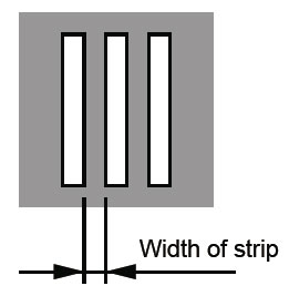
The gap between the holes is called “width of strip”. (see Fig.1)
If there is not enough width of strip, twist and deformation occur in “part of strip”.
Usually, the width of strip needs,
- ・For Mild steel and Aluminum, more than twice the plate thickness.
- ・For Stainless steel, more than 4 times the plate thickness.
ADVICE ON ONE POINT
When piercing with a narrow “width of strip”,
- 1.Increase the pressure of the plate.
- 2.Reduce the guide clearance.
etc. please take the measures
Fig.1 width of strip
COUNTERMEASURES FOR BROKEN EDGE OF SMALL DIAMETER PUNCH
Is it possible to pierce 0.8mm hole?
When processing a small hole or a hole smaller than the plate thickness,
it may become unusable due to “Breaking” rather than tool life due to seizure of the blade edge or galling.
Generally, the hole diameter (width) for the plate thickness to be processed,
- ・For Mild steel and Aluminum, more than twice the plate thickness.
- ・For Stainless steel, more than 2 times the plate thickness.
is preferred.
There is a method of shortening the length of the punch blade as a countermeasure against breaking of the blade edge when processing a hole diameter (width) smaller than that.
Normally, there are two types of punch edge lengths, “Standard type” and “Narrow type”,
depending on the blade edge dimensions.
However, when processing small-diameter holes, we recommend “special narrow type”,
“super-narrow type”, or “open-end type” with a shorter cutting edge length to match the thickness of the plate to be processed.
We also have punches for thick material processing.
If you specify the thickness and material of the workpiece to be machined together with the cutting edge dimensions at the time of ordering, we will deliver the optimal mold according to it.
ABOUT THE PROJECTION OF THE MICRO JOINT
Is there anything you can be done about it?
As shown in Fig. 2, by using a joint type that has a shape where the joint is inserted deeper than the material surface,
it is possible to prevent protrusions that protrude outside the outer periphery of the product.
It is also possible to form joints that do not stand out with the liner joint type (LJ tool).
Fig.2 Micro Joint
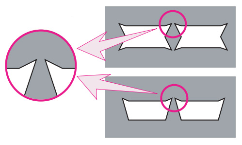
Fig.3 Liner Joint
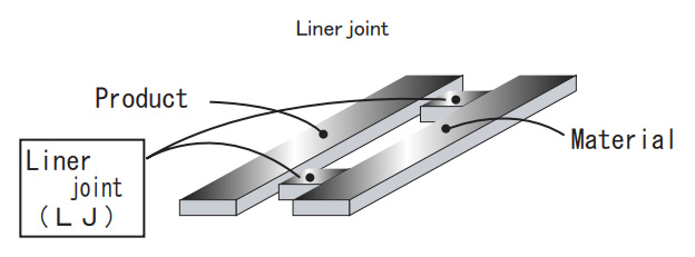
Liner joint tool (LJ tool) is a tool that makes the joints generated by micro joints and wire joints inconspicuous by connecting the base material and the product with half cut joints.
The joint strength can be adjusted by the joint width.
-
vol.1 COUNTERMEASURES FOR SLUG PULLING IN PUNCHING PROCESS
-
vol.2 LIFE COUNTERMEASURE FOR TOOLING
-
Vol.3 TOOL MAINTENANCE
-
Vol.4 FORMING TOOL
-
Vol.5 MATERIAL FOR TOOLING
-
Vol.6 FOR CLEARANCE OF THE CUTTING DIE
-
Vol.7 ABOUT TURRET PUNCH PRESS MACHINE
-
Vol.8 VARIOUS KINDS OF SPECIAL SHAPE
-
Vol.9 PARTS NAME OF STANDARD TOOLING
-
Vol.10 EACH NAMES OF FORMING TOOL
-
Vol.11 MATERIAL PROPERTIES (STEEL)
-
Vol.12 MATERIAL PROPERTIES
-
Vol.13 CALCULATION FORMULAS FREQUENTLY USED IN SHEET METAL
-
Vol.14 HEIGHT ADJUSTMENT FREE TOOL
-
Vol.15 HOW TO DRAW AND READ DRAWINGS
-
Vol.16 HOW TO DRAW AND READ DRAWING (PRACTICAL USE)
-
Vol.17 SHAPE INSTRUCTION FOR FORMING TOOLS(1)
-
Vol.18 SHAPE INSTRUCTION FOR FORMING TOOLS(2)
-
Vol.19 CODE MANAGEMENT
-
Vol.20 BENDING TECHNICAL INFORMATION
-
Vol.21 TECHNICAL COUNSELING FAQ(1) "COUNTERMEASURES FOR GALLING"
-
Vol.22 TECHNICAL COUNSELING FAQ(2) "BURRING FOR THREAD FORM"
-
Vol.23 TECHNICAL COUNSELING FAQ(3) "PITCH OF SINGLE PIERCING"
-
Vol.24 TECHNICAL COUNSELING FAQ(4) "SHEAR OPTIONS"
-
Vol.25 TECHNICAL COUNSELING FAQ(5) "HOLDING MARK"
-
Vol.26 TECHNICAL COUNSELING FAQ(6) "SOLUTION FOR SLUG PULLING OF A SHEET METAL WITH PROTECTIVE FILM"
-
Vol.27 TECHNICAL COUNSELING FAQ(7) "MATERIAL WARPING PREVENTION DURING"
-
Vol.28 TECHNICAL COUNSELING FAQ(8) "WARPING PREVENTION OF BLANKING OUT"
-
Vol.29 TECHNICAL COUNSELING FAQ(9) "COUNTERSINK FOR COUNTERSUNK SCREW"
-
Vol.30 THE ORDERING GUIDE(1) "HOW TO INSTRUCT SHAPE AND DIMENSIONS"
-
Vol.31 THE ORDERING GUIDE(2) "REFERENCE KEY DIRECTION"
-
Vol.32 THE ORDERING GUIDE(3) "ANGLE INDICATION OF ANGLED TOOL"
-
Vol.33 THE ORDERING GUIDE(4) "SELECT SPECIFICATION OF PUNCH"
-
Vol.34 THE ORDERING GUIDE(5) "DIE SPECIFICATION SELECTION"