

vol.7 ABOUT TOOL INSTALLATION
(TOOL INSTALLATION PROCEDURE, ALIGNMENT PROCEDURE)
Due to the mandatory safety measures, safer tool mounting methods have become widespread due to improvements in laser beam safety devices and clamp systems.
For this reason, work accidents have been reduced, but we think that some people still have experience such as “The hand slipped and was dangerous.”
Don't think that "The accident at the time of mounting is not important", please review again and try to work safely.
TOOL INSTALLATION PROCEDURE (Amada type)
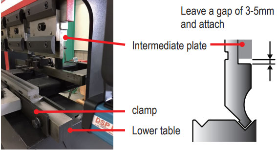
Depending on the type of intermediate plate and clamp,
the number of cases where the punch is“front-inserted” and “front-removed” is increasing,
but this time we will focus on horizontal insertion to emphasize safety.
Follow the steps below to install the tool.
〔 FOR 2V DIE 〕
|
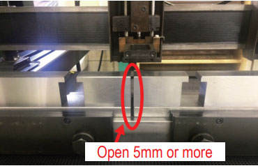
|
|
|
|
|
|
|
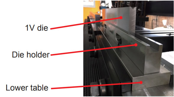
〔 FOR 1V DIE 〕
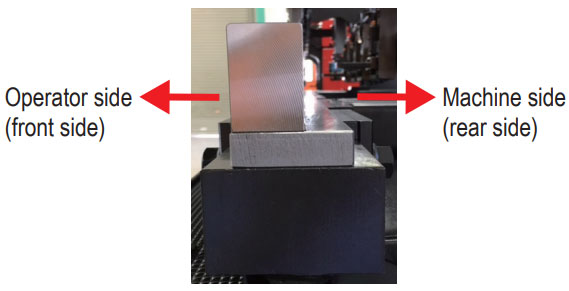
- 1.The die for thin plate (V-width less than 32mm) can be mounted on various types of die holders.
- 2.The die for thick plate (V-width 32mm or more) is directly mounted on the lower table.
However, it may be necessary to attach a die block holder due to the stroke and open height.
* As a common matter, the lower part of the table and the rear part of the die holder base must not be loosened as it is a standard for aligning.
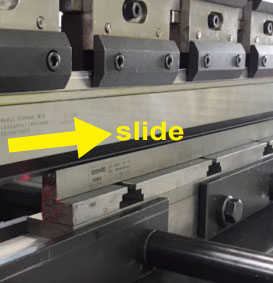
〔 FOR PUNCH 〕
- 1.After attaching the die, place the cutting edge of the punch in the V-groove of the die to be used, and slide it to the desired position.
- 2.After insertion, tighten the front bracket so that the punch does not drop.
* If the punch and die are fixed by shifting the left and right positions by about 5mm, it will prevent scratches. - 3.At present, the one-touch type has become widespread, and mounting from the front is also possible.
However, heavy punches are mounted by sliding in the procedure 1 instead of inserting them from the front for safety reasons.
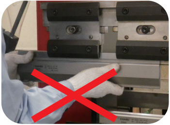
POINT
Holding the underside of the punch may cause injury if dropped.
When mounting from the front, be sure to hold both ends of the tool.
ALIGMENT PROCEDURE
(Excluding one-touch type) * For details, follow the procedure in the machine's instruction manual.
- 1.Operate the machine with the punch and die attached, and apply a pressure of about 1 to 2 tons.
Adjust the amount of pressurization according to the tool length.
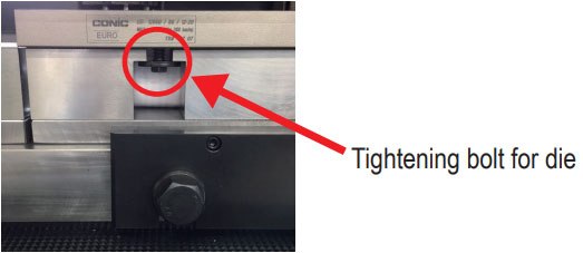
Watch out for too much. - 2.While pressurized, tighten the bolt completely to fix the punch.
- 3.Thereafter, the tightening bolts of the die are completely tightened and fixed.
- 4.Release the punch and die slowly and check that the punch and die are not loose.
- * If the edge angle between the punch and the die is different, or if the tip R of the punch is smaller than the V bottom R of the die, misalignment may occur.
In the case of such a aligning, it is better to sandwich paper (newspaper) etc. and tighten the die.
-
vol.1 TYPE OF PRESS BRAKE TOOLS
-
vol.2 ABOUT V - BENDING TYPE
-
vol.3 PREPARATION FOR BENDING 1
(TONNAGE CHART , MINIMUM FLANGE LENGTH, V width selection) -
vol.4 PREPARATION FOR BENDING 2
(Punch marking example, V - BENDING FORCE CALCULATION FORMULA) -
vol.5 THE FEATURES OF BENDING
(BENDING ALLOWANCE, SPRING - BACK) -
vol.6 ABOUT TOOL SELECTION
(STEPS FOR CHOOSING A TOOL, STUDYING FROM THE DRAWINGS, READ DETAILS FROM DRAWINGS) -
vol.7 ABOUT TOOL INSTALLATION
(TOOL INSTALLATION PROCEDURE, ALIGNMENT PROCEDURE) -
vol.8 PROBLEMS OF BENDING
(DIMENSIONAL DEFECT AND ANGLE DEFECT, GUIDELINS FOR RE-POLISHING, COUNTERMEASURES OTHER THAN REGRINDING) -
vol.9 PROBLEMS OF BENDING 2
(ANGLE DEFECT, MACHINE MAINTENANCE) -
vol.10 PROBLEMS OF BENDING 3
(COUNTERMEASURE FOR CRACK / FRACTURE) -
vol.11 PROBLEMS OF BENDING 4
(SPRING-BACK MEASURES, WORK WARPAGE MEASURES, SHEARING METHOD AND WARPAGE TENDENCY BY SHEET METAL MACHINE) -
vol.12 TYPES OF BENDING SHAPES
(HEMMING BENDING, STEP BENDING) -
vol.13 BENDING FAQ 1
(TOOL INTERFERENCE, MINIMUM FLANGE LENGTH) -
vol.14 BENDING FAQ 2
(ABOUT TOOL SELECTION) -
vol.15 ABOUT TOOL MANAGEMENT
(EXAMPLE OF TOOL MANAGEMENT, EXTENDING TOOL LIFE) -
vol.16 PROBLEMS OF BENDING
-
vol.17 PROBLEMS OF BENDING
(BENDING BUMP MEASURES) -
vol.18 PROBLEMS OF BENDING