

vol.14 BENDING FAQ 2
(ABOUT TOOL SELECTION)
This time, following on from Technical Guidance Vol-PB.13, we will pick up and explain the content you inquired about.
ABOUT TOOL SELECTION
- Q:Is there a way to make tool selection easy?
- A:When selecting a tool, it is necessary to consider the machine specifications, V-width,
combination, bending order, and required pressure.
This time, we will summarize and explain the guidelines. For the basic tool selection procedure,
see Technical Guidance Vol-PB.6.
〔 PUNCH SELECTION CRITERIA 〕
1. Interference:
Use the “press brake tool cross-sectional shape sheet” and “bending limit graph” to check whether the tool work interferes and determine the tool shape.
(See Technical Guidance Vol. 13)
2. Tip R:
R of the product is determined by “ir ≒ V/6”.
For the tip R, select an R that is slightly smaller than the inner R.
For the tip R, R0.2 is often selected, but...
- ■Advances in machinery have enabled highly accurate alignment.
- ■I want to make the tip angle gentle and minimize wear on the cutting edge.
For these reasons, there are cases where the tip R0.6 is used even when processing thin sheets.
3. Punch angle: (In case of 90° bending with bottoming)
| Material | Thickness | Angle | Effect |
|---|---|---|---|
| Mild steel plate / Thin plate | ~2.0mm | 88°・ 90° | Small effect of spring-back |
| SUS / AL / Thickness plate |
88°→ 84°→ 82° | Since the effect of spring-back is large, select a slightly sharp tip angle. |
〔 DIE SELECTION DRITERIA 〕
Selection of 88° die and 90° die
| Material tensile strength | 88°for high material, 90°for low material |
|---|---|
| Spring-back value | 88°for large, 90°for small |
| When performing coining | 90° |
The above is a basic guideline for selecting standard punches and dies.
When processing, be sure to perform preliminary verification such as trial bending to confirm sheet metal quality and safety.
〔 On the hole deformation near the bending line 〕
- Q: I want to perform burring near the bending line, but the pre-hole has been deformed.
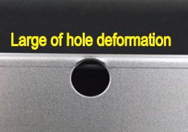
How far should it be from the bending line? - A:The hole near the bending line is easily deformed.
〔 Hole deformation mechanism 〕
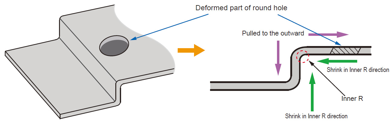
The hole near the bending line is deformed by the force shown above.
The smaller the inner radius, the greater the force that extends outward on the outer radius and the greater the degree of deformation.
The distance (f) that is not affected by hole deformation can be obtained by the following formula.
f = material thickness x 1.5 + R
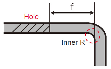
f: Distance from end of hole to inside of bend
Inner R: Inner R of bending
- ◆You can calculate the distance that is not affected by the above formula, but it is a reference value because there are errors depending on the thickness, material, and hole size.
- ◆For hole dimensions with tight dimensional tolerances, allow a margin of +1.0mm or more for the plate thickness from the f-value obtained by the above formula.
- ◆“Sagging” and “burr” also affect the finished dimensions of holes. “Consider bending direction” and “Finish the cut surface nicely” are also effective.
COUNTERMESURE
〔 Add relief holes 〕
If you need to drill a hole near the bend line, you can reduce the deformation of the hole by forming a relief hole on the bend line.
Without relief holes
With relief holes
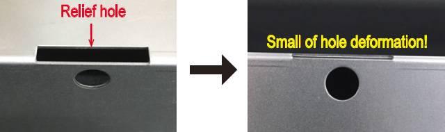
Since the pulling force of the board is not transmitted to the hole, deformation of the hole can be suppressed.
When making relief holes, consider the product appearance, relief hole shape and distance in advance.
PDF Download
-
vol.1 TYPE OF PRESS BRAKE TOOLS
-
vol.2 ABOUT V - BENDING TYPE
-
vol.3 PREPARATION FOR BENDING 1
(TONNAGE CHART , MINIMUM FLANGE LENGTH, V width selection) -
vol.4 PREPARATION FOR BENDING 2
(Punch marking example, V - BENDING FORCE CALCULATION FORMULA) -
vol.5 THE FEATURES OF BENDING
(BENDING ALLOWANCE, SPRING - BACK) -
vol.6 ABOUT TOOL SELECTION
(STEPS FOR CHOOSING A TOOL, STUDYING FROM THE DRAWINGS, READ DETAILS FROM DRAWINGS) -
vol.7 ABOUT TOOL INSTALLATION
(TOOL INSTALLATION PROCEDURE, ALIGNMENT PROCEDURE) -
vol.8 PROBLEMS OF BENDING
(DIMENSIONAL DEFECT AND ANGLE DEFECT, GUIDELINS FOR RE-POLISHING, COUNTERMEASURES OTHER THAN REGRINDING) -
vol.9 PROBLEMS OF BENDING 2
(ANGLE DEFECT, MACHINE MAINTENANCE) -
vol.10 PROBLEMS OF BENDING 3
(COUNTERMEASURE FOR CRACK / FRACTURE) -
vol.11 PROBLEMS OF BENDING 4
(SPRING-BACK MEASURES, WORK WARPAGE MEASURES, SHEARING METHOD AND WARPAGE TENDENCY BY SHEET METAL MACHINE) -
vol.12 TYPES OF BENDING SHAPES
(HEMMING BENDING, STEP BENDING) -
vol.13 BENDING FAQ 1
(TOOL INTERFERENCE, MINIMUM FLANGE LENGTH) -
vol.14 BENDING FAQ 2
(ABOUT TOOL SELECTION) -
vol.15 ABOUT TOOL MANAGEMENT
(EXAMPLE OF TOOL MANAGEMENT, EXTENDING TOOL LIFE) -
vol.16 PROBLEMS OF BENDING
-
vol.17 PROBLEMS OF BENDING
(BENDING BUMP MEASURES) -
vol.18 PROBLEMS OF BENDING