

vol.3 PREPARATION FOR BENDING 1
(Punch marking example, V - BENDING FORCE CALCULATION FORMULA)
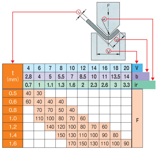
HOW TO READ THE TONNAGE CHART
Check the tonnage chart before Bending.
The tonnage chart is always specified in the tool catalog, and is also displayed on the machine as a nameplate where it is easy to see. Basically, you can read the conditions other than pressure in the chart below.
Knowing this tonnage chart deeply or shallowly will make a big difference in worker safety and product finish.
It greatly affects machine specifications, tool selection, product accuracy and quality, so let's grasp the contents and use them for safe work. First of all, read the following contents from the chart below.
- 1:Minimum flange length (b)
- 2:V-width (V-opening) of tool used for bending (V)
- 3:Required tonnage to bend 1m long material (F)
〔 Right figure, symbol of tonnage chart 〕
V = V-width (V-opening)
b = Minimum flange length
ir = Inner bend radius
t = Material thickness
(Tensile strength 40~50kg/mm)
*Tensile strength for Stainless steel (Inox)
60~75kg/mm, Aluminum 25~45kg/mm
F = Pressure par meter (kN/m)
The values in the tonnage chart are based on "bottoming" and "SS material", so the tensile strength etc.
must be taken into account depending on the processing conditions.
MINIMUM FLANGE LENGTH
To complete the bending, the material must be on both shoulders of the die to the end.
The minimum flange length is expressed by the following formula based on 90° bending.

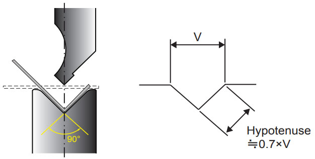
V width selection and basic setting of ir (inner R)
V-WIDTH
| Bending Method | V-Width | Features | ||
| Bottoming | Material thickness | Because of the bending process that is used most often, the patterns for V-grooves are also finely divided. | ||
| 0.5 - 2.6 | 3.0 - 8.0 | 9.0 - 10 | ||
| 6 × t | 8 × t | 10 × t | ||
| Partial Bending | 12 - 15 × t | Since an arbitrary angle bending is taken into consideration, the V-width is set so that bending accuracy is easily stabilized. Approximately twice as much as bottoming. | ||
| Coining | 5 - 6 × t | The purpose is to reduce inner radius and reduce the amount of bite at the tip of the punch. | ||
| Bending Method | V-Width | Features | ||
| Bottoming | Material thickness | Because of the bending process that is used most often, the patterns for V-grooves are also finely divided. | ||
|
0.5 - 2.6 |
3.0 - 8.0 | 9.0 - 10 | ||
|
6 × t |
8 × t |
10 × t |
||
| Partial Bending | 12 - 15 × t | Since an arbitrary angle bending is taken into consideration, the V-width is set so that bending accuracy is easily stabilized. Approximately twice as much as bottoming. | ||
| Coining | 5 - 6 × t | The purpose is to reduce inner radius and reduce the amount of bite at the tip of the punch. | ||
iR (inner radius)
| Bending Method | iR (inner radius) |
Features |
| Bottoming | ≒V/6 | Base values for maintaining safe and stable accuracy, such as punch tip radius and spring-back amount. |
| Partial Bending | When high accuracy is required, use a bottoming type tool. | |
| Coining | Care must be taken when using a bottoming die because iR increases and extra pressurization is required. |
*This chart is only a guide and the final verification should be determined in consideration of other conditions.
Relationship between P (Required tonnage) and t (Material thickness)
As discussed in detail in Vol.4, the relation between tonnage and material thickness is particularly easy to be misunderstood.
Some people think that “the pressure is doubled because the material thickness is doubled”, but this is wrong.
The tonnage chart below shows a part of the required tonnage when the material width is changed while keeping the V-width constant.
It can be seen that when the material thickness is doubled, the tonnage is approximately quadrupled.
The tonnage increases in proportion to the square of the change in thickness, and is not a mere proportional relationship.
Relationship between tonnage and material thickness
| V = 12 | V = 16 | |||
| t (mm) | 1 | 2 | 1.2 | 2.3 |
| P (ton) | 6 | 22 | 6 | 27 |
PDF Download
-
vol.1 TYPE OF PRESS BRAKE TOOLS
-
vol.2 ABOUT V - BENDING TYPE
-
vol.3 PREPARATION FOR BENDING 1
(TONNAGE CHART , MINIMUM FLANGE LENGTH, V width selection) -
vol.4 PREPARATION FOR BENDING 2
(Punch marking example, V - BENDING FORCE CALCULATION FORMULA) -
vol.5 THE FEATURES OF BENDING
(BENDING ALLOWANCE, SPRING - BACK) -
vol.6 ABOUT TOOL SELECTION
(STEPS FOR CHOOSING A TOOL, STUDYING FROM THE DRAWINGS, READ DETAILS FROM DRAWINGS) -
vol.7 ABOUT TOOL INSTALLATION
(TOOL INSTALLATION PROCEDURE, ALIGNMENT PROCEDURE) -
vol.8 PROBLEMS OF BENDING
(DIMENSIONAL DEFECT AND ANGLE DEFECT, GUIDELINS FOR RE-POLISHING, COUNTERMEASURES OTHER THAN REGRINDING) -
vol.9 PROBLEMS OF BENDING 2
(ANGLE DEFECT, MACHINE MAINTENANCE) -
vol.10 PROBLEMS OF BENDING 3
(COUNTERMEASURE FOR CRACK / FRACTURE) -
vol.11 PROBLEMS OF BENDING 4
(SPRING-BACK MEASURES, WORK WARPAGE MEASURES, SHEARING METHOD AND WARPAGE TENDENCY BY SHEET METAL MACHINE) -
vol.12 TYPES OF BENDING SHAPES
(HEMMING BENDING, STEP BENDING) -
vol.13 BENDING FAQ 1
(TOOL INTERFERENCE, MINIMUM FLANGE LENGTH) -
vol.14 BENDING FAQ 2
(ABOUT TOOL SELECTION) -
vol.15 ABOUT TOOL MANAGEMENT
(EXAMPLE OF TOOL MANAGEMENT, EXTENDING TOOL LIFE) -
vol.16 PROBLEMS OF BENDING
-
vol.17 PROBLEMS OF BENDING
(BENDING BUMP MEASURES) -
vol.18 PROBLEMS OF BENDING