

vol.13 BENDING FAQ 1
(TOOL INTERFERENCE, MINIMUM FLANGE LENGTH)
This time, we will pick up the contents of the inquiry and explain it.
TOOL INTERFERENCE
- Q:When bending, the die interfered with the work, so the processing was interrupted and the setup was repeated.
Is there any way to know if the tool does not interfere in advance?
Method 1
There is a method of verifying the “press brake tool cross-sectional shape sheet” by applying it to the product or actual size drawing.
Method 2
Use the “bending limit graph” to understand in more detail.
Method 3
Using “CAD”, it is also possible to select the bending order and tool selection.
Press brake tool cross-sectional shape sheet image

MINIMUM FLANGE LENGTH
- Q:What is the minimum flange size for V-bending?
- A:The minimum flange length of V-bending means the dimension that must be on the die to the end in order to prevent the workpiece from coming off the shoulder of the die and becoming unable to bend during bending.
Be careful not to confuse the minimum flange length with the minimum product height.
Minimum flange length = Minimum height for V-bending
Minimum product height = Minimum height of bending product
Define and explain as above.
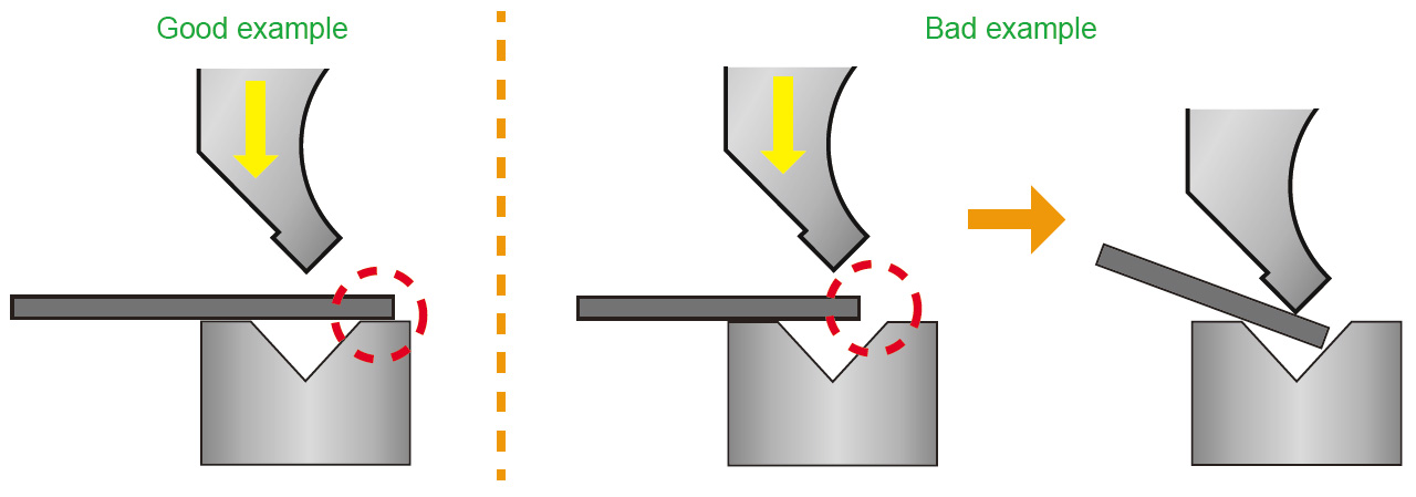
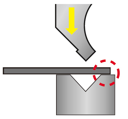
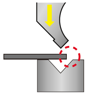
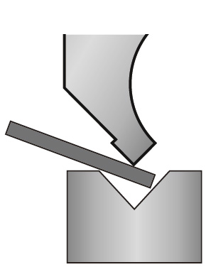
[ Minimum flange length for V-bending ]
As shown in the figure below, the V-bending process cannot be bent unless the edges of the V-bending plate are firmly attached to both sides of the die V-groove.
The minimum flange length depends on the V-groove width of the die used.
Method 1
Calculated with Minimum flange length (b) ≒ 0.7V (V = V-width of die)
Method 2
The following methods are also available for considering the finishing conditions such as material,
the quality of material, and inner radius.
H = R + 3t
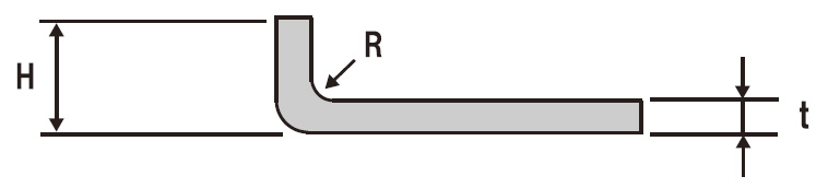
- H:Minimum flange length
- t:Material thickness
- R:Inner Radius
Normally, the minimum flange needs to be about 3 times the plate thickness, so for example, it may be difficult to bend a thin product such as a partial bend or an electronic component.
POINT
By changing to the “Wipe bending method”, the length can be made smaller than the minimum flange length. We propose the following dedicated tools.
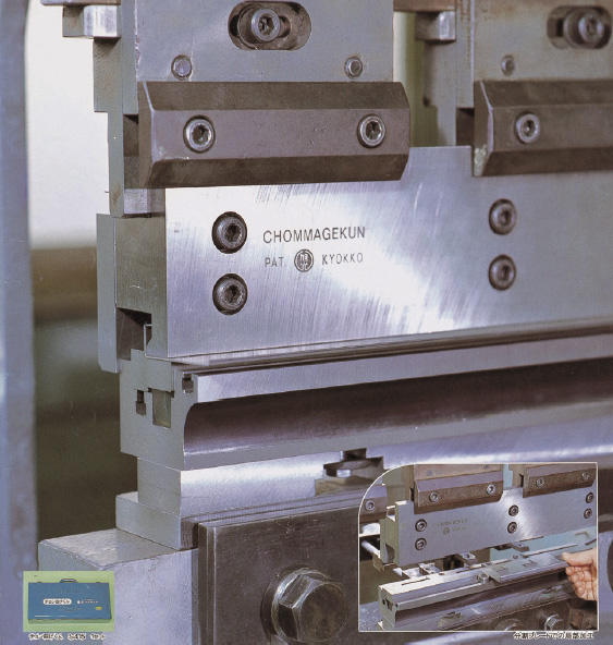
PREVENTIVE PRODUCT
CHOMMAGEKUN
A small rising bend (1.5 times the plate thickness) can be processed quickly.
When changing the work thickness, the bending setting can be easily changed simply by replacing the shim with the same thickness as the product.
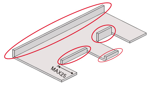
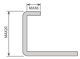
In addition to a small rise, it can be bent as shown below.
* Please contact us in advance as some countries may not be available for sale.
-
vol.1 TYPE OF PRESS BRAKE TOOLS
-
vol.2 ABOUT V - BENDING TYPE
-
vol.3 PREPARATION FOR BENDING 1
(TONNAGE CHART , MINIMUM FLANGE LENGTH, V width selection) -
vol.4 PREPARATION FOR BENDING 2
(Punch marking example, V - BENDING FORCE CALCULATION FORMULA) -
vol.5 THE FEATURES OF BENDING
(BENDING ALLOWANCE, SPRING - BACK) -
vol.6 ABOUT TOOL SELECTION
(STEPS FOR CHOOSING A TOOL, STUDYING FROM THE DRAWINGS, READ DETAILS FROM DRAWINGS) -
vol.7 ABOUT TOOL INSTALLATION
(TOOL INSTALLATION PROCEDURE, ALIGNMENT PROCEDURE) -
vol.8 PROBLEMS OF BENDING
(DIMENSIONAL DEFECT AND ANGLE DEFECT, GUIDELINS FOR RE-POLISHING, COUNTERMEASURES OTHER THAN REGRINDING) -
vol.9 PROBLEMS OF BENDING 2
(ANGLE DEFECT, MACHINE MAINTENANCE) -
vol.10 PROBLEMS OF BENDING 3
(COUNTERMEASURE FOR CRACK / FRACTURE) -
vol.11 PROBLEMS OF BENDING 4
(SPRING-BACK MEASURES, WORK WARPAGE MEASURES, SHEARING METHOD AND WARPAGE TENDENCY BY SHEET METAL MACHINE) -
vol.12 TYPES OF BENDING SHAPES
(HEMMING BENDING, STEP BENDING) -
vol.13 BENDING FAQ 1
(TOOL INTERFERENCE, MINIMUM FLANGE LENGTH) -
vol.14 BENDING FAQ 2
(ABOUT TOOL SELECTION) -
vol.15 ABOUT TOOL MANAGEMENT
(EXAMPLE OF TOOL MANAGEMENT, EXTENDING TOOL LIFE) -
vol.16 PROBLEMS OF BENDING
-
vol.17 PROBLEMS OF BENDING
(BENDING BUMP MEASURES) -
vol.18 PROBLEMS OF BENDING