

CALCULATION FORMULAS FREQUENTLY USED IN SHEET METAL
TONNAGE CALCULATION
In the punch press machine, the allowable tonnage depending on the machine.
Use the calculation formula below to prevent from over tonnage.

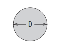
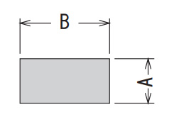
Circumference
| Round | Shaped |
| Diameter x 3.14 | (Length dimension + Width dimension) x 2 |
|
|
| Circumference = D x 3.14 | Circumference = (A + B) x 2 |
Shear resistance by material
| Material | Shear resistance (kg/mm²) |
| Mild Steel | 400 |
| SS400 | 450 |
| Stainless Steel | 600 |
| Aluminum | 200 |
| Copper | 300 |
| Brass | 400 |
Calculation example
The tonnage when piercing Φ40 to Mild Steel T=1.6mm.

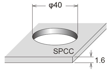
If you do not know the shear resistance, please use about 80% of the shear resistance = tensile strength as a standard.
CALCULATION FORM
* After entering dimensions and plate thickness, select the material and press the Calculate button.
ADVICE ON ONE POINT
If the tonnage exceeds the allowable tonnage of the machine,
reduce the tonnage by the following method.
- 1.Put shear angle on punch edge. (Allows you to reduce tonnages around 10 to 50% by shear angle.)
- 2.Piercing several times. (Reducing tonnages by piercing several times)
- 3.When using cluster tooling, the tonnages can be reduced by making a difference in length of punch that makes same effect as shear angle.
MAKE A SELECTION OF TOOL STATION
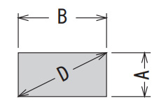
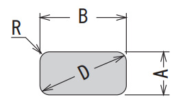
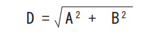
Calculation of the diameter (diagonal dimension) of the cutting edge circumscribed circle is required to select the tool station.
Calculation of diameter (diagonal dimension) of cutting edge circumscribed circle
| Rectanglar shape | Rectanglar shape with radius |
|
|
|

|
| Rectanglar shape |
|
|
|
|
| Rectanglar shape with radius |
|
|
|
|
ADVICE ON ONE POINT
Normally, the size of the tool station is determined by calculating the dimension of the cutting edge circumscribing circle using the above formula and then comparing it with the turret layout.
However, when processing thick materials, it is necessary to increase the station size by one size to prevent from miss stripping.
CALCULATING PRE-HOLE DIMENSION FOR FORMING
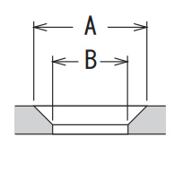
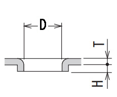
When forming processing, pre-holes may be processed as pre-processing.
In that case, please calculate pre-holes referring to the following calculation formula.
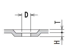
Calculating pre-hole dimension for forming (Reference value for SPCC)
| Chamfering | Burring | Burring for tapping | Emboss | ||
| Size | Inner Dia. | Pre-hole | |||
|
|
M2.6 | φ2.1 | φ1.2 |
|
| M3 | φ2.6 | φ1.5 | |||
| M4 | φ3.4 | φ2.0 | |||
| M5 | φ4.3 | φ2.4 | |||
| M6 | φ5.1 | φ2.8 | |||
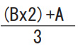
Pre-hole =
|
Pre-hole = D+1.8xT-2xH |
Other dimension, Pre-hole = 0.53 x D + 0.1 |
Other dimension, D-(0.6-0.16xT)xH |
||
| Chamfering | Burring | Emboss |
|
|
|
|
| Burring for tapping | ||
| Size | Inner Dia | Pre-hole |
| M2.6 | φ2.1 | φ1.2 |
| M3 | φ2.6 | φ1.5 |
| M4 | φ3.4 | φ2.0 |
| M5 | φ4.3 | φ2.4 |
| M6 | φ5.1 | φ2.8 |
| Chamfering | Burring | Emboss |
|
Pre-hole =
|
Pre-hole = D+1.8xT-2xH |
Other dimension, D-(0.6-0.16xT)xH |
| Burring for tapping | ||
| Size | Inner Dia | Pre-hole |
|
Other dimension, Pre-hole = 0.53 x D + 0.1 |
||
ADVICE ON ONE POINT
Although forming shape is same, pre-hole dimension would be different depending on material.
It is recommended that you try trial machining with reference to the above equation to obtain proper pre-hole dimension.